Dass Problem hierbei ist einfach der Umstieg von X zu Wayland denn unter Wayland funktionieren die alten Session Restore Funktionen nicht mehr.
Und die DE haben diesen Punkt nicht ganz oben auf ihrer Agenda stehen, also muss man zu Zusatz Apps greifen.
Ich weiß nicht wie es bei Gnome ist, bei KDE soll diese Funktion jedoch mit Plasma 6 wieder funktionieren.
Vielen Lieben dank faxxy für die Info 👍🏼 da ich speziell kein Wayland Gerüst nutze in meiner GNU/Linux-Distro KDE-Plasma also nur X11-org ist mit das mit dem Fensterheber-Problem nicht aufgefallen.
zu deiner Antwort im Thread #9 "Device-1: NVIDIA GM107 [GeForce GTX 745] vendor: PC Partner / Sapphire driver: nvidia" <- es gibt keinen Board -Partner namens Sapphire!
Der einzigste Board-Partner damals im Jahre 2003 - 2004 da war noch zu Zeit des Nvidia nForce-Chipsatzes da gab es ein taiwanesischen Board-Partner namens XFX die hatten für Nvidia damals GeForce Grafikkarten als Board-Partner gebaut aber niemals Sapphire die waren schon zu ATI-Zeiten 1997 immer ATI-Board-Partner natürlich ab 2012 dann AMD Board-Partner Sapphire, deswegen stellt der taiwanesische Board-Partner seitens AMD auch heute in 2023 keine Nvidia Grafik-Chips her. Hier mal alle Vendors zu dem damaligen Nvidia Board-Partnern und heute die Liste ist lang es geht ja nur um den Vendor 10DE "GeForce GTX 745" Nvidia Chip ist der "GM107" auf Maxwell-Architektur. Und hier die Quell zur GeForce GTX 745 von Techpowerup -> https://www.techpowerup.com/gpu-specs/gefo…x-745-oem.c2561.
Zu deinem Thread #10
Wo du den Screenshot gepostet hast.
Du hast ja noch die Erstausstatter Knopfzelle drin von KTS diese Zinkfluzelle ist schon set 2010 auf dem Mainboard diese Tauscht man auch alle drei Jahre mal aus der name der Zinkluftzelle nennt sich CR2032!
Ganz rechts an dem Gehäuse Ende also am Super I/O hast du auch noch einen HD15 (VGA-Ausgang) wenn deine Intel CPU eine IGPU-Einheit besitzt ist das wenn die Dezidierte Grafikkarte mal aussteigt egal dann kannst du immer im BIOS auf die IGPU Umschalten.
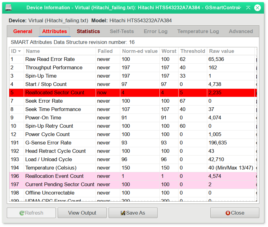
Zu deinem Fehlerbericht bei Thread #11 "Das die Grafikkarte der Übeltäter ist glaube ich nicht" da du ja noch eine Magnetische-Festplatte verbaut hast die habe ich zwar jetzt rot markiert auf deinen Screenshot diese kann für das Flackern der Bildausgabe der Verursacher sein denn der Stellmotor der Magnetischen-Festplatte sehr beansprucht wurde im Laufe der Zeit ist es nur noch ein Frage der Zeit das die HDD austeigt das nennt sich dann auch Click of Death! Die HDD sitzt bei dir im unteren Laufwerksschacht das ist das Schwarze 3,5" Dingensbummens 🤪.
Mach mal folgendes baue mal die Platte aus und schaue mal bitte auf dem Factory Sticker der Festplatte welches Datum dort auf den Aufkleber gedruckt ist dann poste mal bitte hier im Forum die CAS Werte der Festplatte dies kannst mit dem Tool (Werkzeug) namnes GsmartControl ermitteln posten dann die Werte aus dem Tool GsmartControl hier im Forum. Hier die Quell zum GsmartControl Tool -> https://github.com/ashaduri/gsmartcontrol/releases
Wenn du das GsmartControl Tool in deiner Linux-Distro installiert und gestartet hast.
Lade zu erst das GsmartControl Tool von Github herunter.
Dana öffnest du eine Konsole oder Terminal deiner wahl
Navigiere nun in Terminal zu deinem Download-Ordner also cd /home/dein-benutzer-name/Downloads/
Schreibe nun folgenden Befehl ins Terminal um den gepackten bz2-File zu entpacken.
tar -xf gsmartcontrol-1.1.4.tar.bz2
Nun wird der Komprimierte Datei entpackt navigiere nun in den entpackten Ordner namens gsmartcontrol 1.1.4
Überprüfe vorher im Terminal ob du ggf. das Install-Skript noch ausführbar machen musst!
das sieht man im Terminal an den Attribvuten einer Datei -r- <- read -w- <- write -x- <- execute!
Führe nun folgenden Befehl im Terminal aus um das GsmartControl Tool zu Installieren
sudo ./install.sh
Wähle dann das Laufwerk aus in deinem Fall die HDD wenn im GsmartControl rote Markierungen dir angezeigt werden ist das kein gutes Zeichen für deine HDD!
Falls du noch Fragen hast dann frage ruhig :-).
Und ganz ganz Wichtig stelle Bitte in deinem BIOS den Schalter Smart <- auf enabled!
Kleine Randnotiez noch es kann bei manchen Linux-Distro zu Kompatibilitätsprobleme kommen wenn im BIOS der Schalter CSM "Compatibility Support Module" aktiv ist!
"The Compatibility Support Module allows legacy operating systems and some legacy option ROMs that do not support UEFI to still be used. It also provides required legacy System Management Mode (SMM) functionality, called CompatibilitySmm, as an addition to features provided by the UEFI SMM." -> https://en.wikipedia.org/wiki/UEFI#:~:t…he%20UEFI%20SMM.
Was für mich so aus meiner Jugend eine Ikone der EBM-Techno Szene ist und heute auch nicht ist Thomas Peter Heckmann auch unter dem Alias "Knarz" bekannt das Liedchen "Kind der NAcht" aus dem Jahre 2000 -> https://www.discogs.com/de/master/1084…-Kind-Der-Nacht 🤪 gerade lyrisch hatte mir diese Minimal-Techno Stück gut gefallen "Deine roten Augen haben mich angelacht ......Kokain ist dein Ruin .....du bist ein Kind der........du bist ein Kind der Nacht.
Inhalte von externen Seiten werden ohne Ihre Zustimmung nicht automatisch geladen und angezeigt.
Durch die Aktivierung der externen Inhalte erklären Sie sich damit einverstanden, dass personenbezogene Daten an Drittplattformen übermittelt werden. Mehr Informationen dazu haben wir in unserer Datenschutzerklärung zur Verfügung gestellt.
ja das stimmt die ersten Deutschen Linux-Bücher zu GNU/Linux-Systemen waren so 350 Seiten dick damit, konnte man nicht nur seinen CRT-Monitor wenn der Monitor-Fuss gefehlt hatten das Linux-Buch als Monitor-Stütze benutzen 🤪 sondern auch wenn es mal Probleme gab mit der Shell oder BASH das Linux-Buch als Tastatur-Hammer benutzen <-Ironie-Modus aus ja die damalige Linux-Lektüre war echt klasse heute sind ja ePUB oder andere eBooks zu Linux ganz anders Aufgebaut was und auch die Thematik schreckt vielleicht auch den einen oder anderen Linux-Neuling ab aber wer auch in Windows....hust......:-) Meinte Fenster-OS schon in der Eingabeauffordeung kurz CMD ist ja auch eine C-Shell gearbeitet hat der wird sich schnell in einer BASH gut zurechtfinden. Finde es klasse immer mal hier die Erfahrungen von anderen Linuxern und Linuxerinnen hier im Forum zu lesen echt klasse 👍🏼.
das freut mich wenn du ein Fenstererkennungs-Programm namens Devil´s_Pie -> https://wiki.ubuntuusers.de/Devilspie/ gefunden hast um deine Fenster-Problematik damit besser im Alltag und im Umgang damit klar zu kommen 👍🏼. Ich habe ein Fenster-Debugger unter GNU/Linux noch nie gebraucht bringen nicht eigentlich auch die Fenstermanager-Systeme wie Herbstluft und Bspwm ist eigenen Fenster-Debugger mit? Ihr könnt mich ja gerne mal Aufklären ob diese Fenster-Manager auch ihre eigenen Debugger als SDK-Kit mitbringen :-).
ab der 22.ten Minute das Liedchen von Mila Dietrich vs. The Hacker "mir fällt gerade nur nicht der Lied-Titel ein Schande über mein Haupt 🤪" ja kenne ich ist schöner Dark Techno.
Inhalte von externen Seiten werden ohne Ihre Zustimmung nicht automatisch geladen und angezeigt.
Durch die Aktivierung der externen Inhalte erklären Sie sich damit einverstanden, dass personenbezogene Daten an Drittplattformen übermittelt werden. Mehr Informationen dazu haben wir in unserer Datenschutzerklärung zur Verfügung gestellt.
hier mal was komplett anderes von Mila Dietrich schöner Dark Neowave viel Spass mit dem Liedchen "Drive and Cry" wünscht Schatten-Nacht 🖐🏼 👍🏼.
vielen Lieben Dank für deine Antwort auf das kultige Musik-Video mit "Marti Fischer & Jan Philip Zymny - Wir Sind Dumm" 🤪.
Ich finde es solche Kunst echt Klasse und mich stört es auch nicht das solche Musik-Videos eher eine Nische Darstellen als wie, für die breite Masse zur Mainstream-Musik.
Ich habe noch ein Klassiker of Hip-Hop von derHip-Hop Band "Die Firma"
Inhalte von externen Seiten werden ohne Ihre Zustimmung nicht automatisch geladen und angezeigt.
Durch die Aktivierung der externen Inhalte erklären Sie sich damit einverstanden, dass personenbezogene Daten an Drittplattformen übermittelt werden. Mehr Informationen dazu haben wir in unserer Datenschutzerklärung zur Verfügung gestellt.
👌🏼 ich hatte damals auch das Album namens "Krieg und Frieden" aus dem Jahr 2005 auf Schallplatte.
Hier mal meine Wertanlage von der Synth-Pop / EBM-Band Covenant - Northern Light aus dem Jahr 2002 Doppel Vinyl von K2 Records -> https://www.discogs.com/de/release/103…-Northern-Light steht bei Discogs.com schon bei knapp 300€ zum Verkauf das Album "Northern Light" war aber auch schon bei Discogs.com für 500€ zum Verkauf also new unplayed drin. Ich habe das Album zweimal einmal als Schallplatten EP und einmal als CD Album zum dauer hören 🤪 👌🏼.
Inhalte von externen Seiten werden ohne Ihre Zustimmung nicht automatisch geladen und angezeigt.
Durch die Aktivierung der externen Inhalte erklären Sie sich damit einverstanden, dass personenbezogene Daten an Drittplattformen übermittelt werden. Mehr Informationen dazu haben wir in unserer Datenschutzerklärung zur Verfügung gestellt.
"Covenant - Bullet" eine kleine Hommage an Depeche Mode 👌🏼.
ich Bitte um Hilfe ich suche einen XUL-Debugger für GNU/Linux kann aber keinen finden da die MZN (Mozilla Foundation) das "XULRunner-Projekt" eingestellt hat gibt es trotzdem eine Möglichkeit oder eine Alternative für GNU/Linux was den XULRunner betrift?
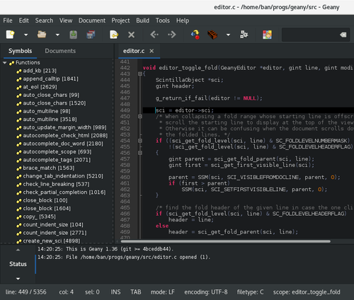
Hier mal ein Link für das bessere Verständnis -> https://wiki.mozilla.org/XULRunner , https://developer.mozilla.org/en-US/docs/Moz…ts_in_Firefox_3 <- es geht mir nicht um den Firefox sondern eher um die Fritzbox diese arbeitet auch mit LUA-Skripten und XUL-Skripten und ich wollte mal einen meiner Login prüfen dafür benötige ich aber ein XUL-Debugger weil, der Firefox DOM-Inspector oder der Google Chrome DEV-Inspector mir nur das Skript anzeigt aber eben nicht die LUA oder XUL-Funktionen (Struktur) innerhalb des Objekts.
Hier ein Screenshot dazu ->
Und hier mal ein Screenshot innerhalb auf der Web-API meiner Fritzbox ->
Ich hoffe es kann mir jemand eine Alternative zu dem obsoleten XULRUnner empfehlen.
Inhalte von externen Seiten werden ohne Ihre Zustimmung nicht automatisch geladen und angezeigt.
Durch die Aktivierung der externen Inhalte erklären Sie sich damit einverstanden, dass personenbezogene Daten an Drittplattformen übermittelt werden. Mehr Informationen dazu haben wir in unserer Datenschutzerklärung zur Verfügung gestellt.
Auf Discogs können Sie sich ansehen, wer an 2016 CDrvon Gelb mitgewirkt hat, Rezensionen und Titellisten lesen und auf dem Marktplatz nach der Veröffentlichung…
Inhalte von externen Seiten werden ohne Ihre Zustimmung nicht automatisch geladen und angezeigt.
Durch die Aktivierung der externen Inhalte erklären Sie sich damit einverstanden, dass personenbezogene Daten an Drittplattformen übermittelt werden. Mehr Informationen dazu haben wir in unserer Datenschutzerklärung zur Verfügung gestellt.
"Neuroticfish - Why Don't You Hate Me (Remastered) 2016) 👌🏼bin ich Fan-Boy von Neuroticfish 🤪.
Entdecken Sie Songs, Empfehlungen und andere Albumdetails für Trauma: Ritual von [:SITD:]. Vergleichen Sie unterschiedliche Versionen und kaufen Sie alle auf…
www.discogs.com
Hier mal mein Record on a Vinyl https://www.discogs.com/de/release/100…D-Trauma-Ritual | Scanner (2) - SCAN130LP auf meinem LP-Album "Trauma-Ritual ist leider nicht der [Inten:Outtake Remix] drauf bin von [:SITD:] = Shadow Into The Dark auch ganz großer Fan-Boy habe alle Alben und besitze auch die LP Alben von [:SITD:] meine Discographie Stronghold EP (2003), Coded Message: 12 EP (2005), Bestie Mensch EP (2007), Rot EP (2009), Icon:Koru EP (2011), Dunkelziffer EP (2014), Trauma-Ritual EP Vinyl (2017), Stunde X EP Vinyl (2019) 👌🏼.
Inhalte von externen Seiten werden ohne Ihre Zustimmung nicht automatisch geladen und angezeigt.
Durch die Aktivierung der externen Inhalte erklären Sie sich damit einverstanden, dass personenbezogene Daten an Drittplattformen übermittelt werden. Mehr Informationen dazu haben wir in unserer Datenschutzerklärung zur Verfügung gestellt.
Guten Abend und Hallo vs2-free-users echt starkes Hip-Hop Video zu den Kult Zeichentrickserien aus damaliger Zeit fünf ⭐⭐⭐⭐⭐ so muss Hip-Hop 👍🏼 und weil, es so toll ist hier von mir an dich ein Underground Stück by Marti Fischer & Jan Philipp Zymny - Wir Sind Dumm ⭐⭐⭐⭐⭐ Lyrisch sehr sehr geil wie Hip-Hop aus den ninties 🤪 👍🏼 viel Spass.
Inhalte von externen Seiten werden ohne Ihre Zustimmung nicht automatisch geladen und angezeigt.
Durch die Aktivierung der externen Inhalte erklären Sie sich damit einverstanden, dass personenbezogene Daten an Drittplattformen übermittelt werden. Mehr Informationen dazu haben wir in unserer Datenschutzerklärung zur Verfügung gestellt.
Da Jan Philipp Zymny ja eher Kabarett oder Theater Parodien und Texte dazu schreibt ist der kurze Hip-Hop Track der beiden nochmals eine ganz geile Hommage an die frühreren Hip-Hop Zeiten.
LG von Schatten-Nacht 🖐🏼
PS Vielleicht sollte ich aus dem Liedchen auch so ein Motto mir in meine Avatar-Signatur schreiben "Ich Denke nur Scheiße und Furze Ideen" <- Ironie-Modus an 🤪 hat aber trotzdem irgendwas.
Inhalte von externen Seiten werden ohne Ihre Zustimmung nicht automatisch geladen und angezeigt.
Durch die Aktivierung der externen Inhalte erklären Sie sich damit einverstanden, dass personenbezogene Daten an Drittplattformen übermittelt werden. Mehr Informationen dazu haben wir in unserer Datenschutzerklärung zur Verfügung gestellt.
👌🏼Volle Energie und FERTIG ist die Remrod-Infanterie 🤪.
Inhalte von externen Seiten werden ohne Ihre Zustimmung nicht automatisch geladen und angezeigt.
Durch die Aktivierung der externen Inhalte erklären Sie sich damit einverstanden, dass personenbezogene Daten an Drittplattformen übermittelt werden. Mehr Informationen dazu haben wir in unserer Datenschutzerklärung zur Verfügung gestellt.
absolute classic 👌🏼
Und zum Abschluss noch ein kleines Extra von der Band Weimar - Anders als die Andern
Inhalte von externen Seiten werden ohne Ihre Zustimmung nicht automatisch geladen und angezeigt.
Durch die Aktivierung der externen Inhalte erklären Sie sich damit einverstanden, dass personenbezogene Daten an Drittplattformen übermittelt werden. Mehr Informationen dazu haben wir in unserer Datenschutzerklärung zur Verfügung gestellt.
Ich habe einen Artikel gelesen, der zusammengefasst diesen Inhalt hat:
Der Cyber Resilience Act (CRA) der EU könnte Open Source-Software in Europa gefährden, trotz der Ausnahme für nicht kommerzielle Nutzung. Diese vagen Formulierungen verursachen Bedenken in der Open Source-Community. Verstöße gegen den CRA könnten Unternehmen Millionenstrafen einbringen und Open Source-Aktivitäten einschränken. Das würde die Dominanz großer IT-Giganten fördern und die Vielfalt in der europäischen Softwareindustrie gefährden. Es besteht jedoch Hoffnung, dass Verhandlungen und Anpassungen des CRA zu einer positiven Lösung für die Open Source-Community führen können. Dies ist entscheidend, da Open Source eine Schlüsselrolle für Europas IT-Infrastruktur und digitale Souveränität spielt.
Wie seht ihr die Sache, könnte Open-Source-Software wirklich dadurch ins »Hintertreffen« geraten, wie es der Autor beschreibt?
sehr guter Beitrag und nochmals fetten Dank an dich für deine Recherche zur Transparenz in Open-Source und was die EU alles verhunzen will nur damit es Freie-Entwickler schwerer haben ihre Software egal ob Open-Source oder Closed Source für Benutzer / Benutzerinnen umzusetzen was diese CRA Konstrukt wird und wie es Umgesetzt wird, wird die Zeit und die Annahme der Benutzer / Benutzerinnen von Software zeigen da der Artikel nur auf einen CRA-Entwurf gerichtet wird sich wahrscheinlich was die Regularien betrift bei Open-Source Software noch einiges ändern was in dem Artikel noch nicht drin steht.
Zum anderen weiß, hier im Linux-Guides-Forum fast jeder das man auch den Spieß, umdrehen kann im Bezug auf Datendiebstahl bestes Beispiel ist das Betriebssystem der NSA das SELinux hier mal ein kleines Zitat aus Wiki "SELinux ist eine Erweiterung des Linux-Kernels, die den ersten Versuch darstellt, das FLASK-Konzept des US-amerikanischen Geheimdienstes NSA umzusetzen. Es implementiert die Zugriffskontrollen auf Ressourcen im Sinne von Mandatory Access Control." -> https://de.wikipedia.org/wiki/SELinux
Man hat ja auch noch diese Option und eventuell sind auch Freie-Entwickler so gut und benutzen diese Möglichkeit -> "Mandatory access control (MAC) is a model of access control where the operating system provides users with access based on data confidentiality and user clearance levels. In this model, access is granted on a need to know basis: users have to prove a need for information before gaining access."
Zu der Problematik "Identitätsmanagementsysteme" in Windows 12 mit Hilfe der integrierten KI sehe ich da auch sehr sehr bedenklich aber was Microsoft Plant und macht juckt mich nicht mehr da Windows 10 eh mein letztes Microsoft-Betriebssystem ist.
, https://winfuture.de/news,136021.html "Microsoft & AMD bauen gemeinsam KI-Chips - pünktlich zu Windows 12?" <- ich für meinen Teil kann sehr gut auf KI und
Ich bin großer GOG-Fan. Die Spiele von 1999 bis ca.2010 sind eh die Bestern und Innovativsten. Und sie gehören mir. Kleiner Tipp: Es lohnt sich im Auslandsurlaub mal bei GOG zu gucken da gibt dann auch die Spiele, die es aus Gründen *HUST* nicht in Deutschland gibt.
Und mit deiner Aussage das die Spiele aus dem Jahre 1999 - 2010 die Besten sind naja Spiele sind ja "Geschmackssache" wie Musik-Genres und Co. und da stimme ich die Teilweise zu, 2001 - 2010 war für 3D Gaming-Engines eine Blütezeit mal eine kleines Beispiel https://www.pcgamingwiki.com/wiki/Clive_Barker%27s_Undying <- Absoluter Gaming-Klassiker aus dem Jahre 2001 👌🏼 gibt viele Mods zu dem Spiel.


 🖐🏼
🖐🏼 🖐🏼,
🖐🏼,

 🖐🏼
🖐🏼


 🖐🏼
🖐🏼 🖐🏼
🖐🏼 🖐🏼,
🖐🏼, 🖐🏼,
🖐🏼, 🖐🏼,
🖐🏼,